Investigation of the Base-Isolation System Effect on Stress and Base-Shear Force of Curved Bridge According to Soil-Structure Interaction.
Mohammad Ali Lotfollahi-Yaghin1 and Reza Shiri2 *
1
Civil Engineering Faculty,
University of Tabriz,
Tabriz,
Iran
2
Islamic Azad University Maragheh Branch,
Iran
http://dx.doi.org/10.12944/CWE.10.Special-Issue1.125
The present study evaluates the stress of deck and base shear of the isolated curved bridges, in seismic areas by considering the effect of soil-structure interaction. In order to Seismic Isolating of the bridge, double concave friction pendulum bearing are located between the middle columns and supports. The bridge is a three-span curved bridge with concrete box beams on bottom layers of non-cohesive soils with a high depth. Three-dimensional modeling and analysis was performed using ABAQUS software. The created model was non-linear analyzed by the Northridge earthquake. Comparing the results with the results of similar curved bridge with no Seismic isolator indicate that, isolated bridge deck stress and base shear has declined significantly. Therefore seismic isolation systems can improve of performance of structure and prevent damages during earthquakes.
Copy the following to cite this article:
Lotfollahi-Yaghin M. A, Shiri R.Investigation of the Base-Isolation System Effect on Stress and Base-Shear Force of Curved Bridge According to Soil-Structure Interaction. Special Issue of Curr World Environ 2015;10(Special Issue May 2015). DOI:http://dx.doi.org/10.12944/CWE.10.Special-Issue1.125
Copy the following to cite this URL:
Lotfollahi-Yaghin M. A, Shiri R.Investigation of the Base-Isolation System Effect on Stress and Base-Shear Force of Curved Bridge According to Soil-Structure Interaction. Special Issue of Curr World Environ 2015;10(Special Issue May 2015). Available from: http://cwejournal.org?p=775/
Download article (pdf)
Citation Manager
Publish History
Introduction
Seismic isolation systems, in structures and bridges, provide horizontal isolation against horizontal provocations of seismic vibrations.
Double concave fraction pendulum bearing (DCFP) is an innovative seismic isolation system from earlier friction pendulum system. Most of the studies and designs are concentrated on straight bridges, and curved bridges are rarely discussed, while considering the topography of the site of the bridge and some special circumstances, it's also necessary to study on curved bridges [Bahar et al, DeSantiago et al and Constantinou et al]. In recent years, researchers found that the impact of soil surrounding structures basis, particularly bridges is very important on their behavior, and ignoring the Soil-structure interaction effects from the engineering perspective will lead to low safety [Olmos et al and Ates et al]. Hence, in present study, Soil-structure interaction is considered in bridge modeling.
The purpose of this study is to investigate the stress of deck and base shear for bridge with DCFP, which are exposed to the Seismic vibrations, with considering the soil-structure interaction. The three-dimensional model has been used in the process of analysis in order to make a more correct evaluation on the influence of Earthquake and soil-structure interaction on the dynamic response of curved bridge. To achieve this purpose, the ABAQUS software has been used, which has an appropriate computational capability based on the finite element method.
Double Concave Fraction Pendulum Bearing
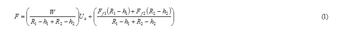
As it’s shown in the figure 1, double concave fraction pendulum bearing consists of two double concave surfaces, which are called Upper and lower surfaces. Concave surfaces may have identical or non-identical radius of curvature. Also, the friction coefficient of these surfaces may be equal to or different from each other. 2d is the maximum displacement of the isolator. d represents the maximum displacement of a concave surface. However, due to the relative rotation of slider, in fact the displacement capacity will be slightly different from 2d. Force- displacement relationship of DCFP isolator is accessible by Equation 1. [Constantinou]:
![Figure 1 - Double concave fraction pendulum bearing [Constantinou]](http://www.cwejournal.org/wp-content/uploads/2015/06/Vol10_Spe_Inves_Moha_Fig1-150x150.jpg) |
|
Where W is the Vertical load, R1 and R2 are the concave surface radius of curvature, h1 and h2 are the height of the slider joint parts and Ub is the total movement (movement of isolator). The sum of Upper and lower surfaces can be calculated in equation 2 [Constantinou]:

Where Ub1 and Ub2 are respectively slider movement at the top and bottom surfaces.
The movement of each surface is calculated by equation 3 and 4 [Constantinou]:
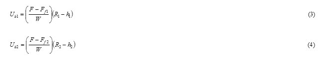
Where Ff1 and Ff2 are respectively, friction force on the upper and lower surfaces.
Friction coefficient of the concave surface is [Constantinou]:

Where fmax and fmin are respectively, maximum and minimum mobilized friction coefficient and a is a parameter that controls the variation of the coefficient with the velocity of sliding.
If we use the seismic isolator with the same curvature radius of the concave surface (R2=R1) and equal height in slider joint parts (h1=h2), then Effective friction coefficient will be equal to the average of µ1 and µ2, and it can be calculated by equation 6 [Constantinou]:

Also the natural period of isolator Vibration can be calculated by equation 7 [Constantinou]:

Where g is the gravity acceleration and Re is the Effective curvature radius.
In this study, Seismic isolator system has been used that, it’s upper and lower concave surface have equal Friction coefficient and Radius of curvature.
soil-Structure Interaction
A soil interaction effect (SSI) on foundation behavior is very important. Ignoring it will lead to a low safety. In the other word, soil with different characteristics will have different behavior. This behavior has important effects of the structure behavior in earthquake. Therefore, relaying on the present and common engineering methods which ignores the soil-structure interaction won’t be without any problem and if these effects are not considered in bridges with Seismic isolator system for analyzing the response of bridge, bearing displacements at abutment locations may be underestimated if the SSI effects are not considered in the response [Tongaonkar and Jangid]. There are many solutions for solving the soil-structure interaction problems, such as Infrastructure and direct solution.
In Infrastructure method, according to the figure 2, the dynamic Soil-structure interaction problem, will be divided to many simple problems, and each sub problem is analyzed by the most appropriate method and then the results will be combined using the principle of superposition of forces. Given to this issue that the Infrastructure method a linear analysis of interaction, to consider the effects of nonlinear behavior of Soil, equivalent linear method can be used [Seed and Idriss].
![Figure 2 - Dynamic Soil-structure interaction using infrastructure method [Wolf]](http://www.cwejournal.org/wp-content/uploads/2015/06/Vol10_Spe_Inves_Moha_Fig2-150x150.jpg) |
|
In direct Soil-structure interaction analysis method, the soil is modeled by the finite element method and a border will be applied around the soil figure. In this method beside the geometric attenuation, Buried rock foundation and soil layering in horizontal and vertical directions can be also considered. According to the mentioned features, in this study the direct solution method for applying the soil-structure interaction effects was used.
Description of the Bridge Under Study and Its Modeling
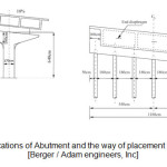
In the present study in order to investigate the seismic response of isolated curved Bridge, the characteristics of the curved bridge in exercise 6, Seismic design phase of Federal Highway Administration (FHWA) by Burgi / Adam Engineering Company, was used [Berger / Adam engineers, Inc]. It should be noted that this bridge has no Seismic isolator. Configuration of this bridge as it’s indicated in figure 3 is a Three-span bridge featuring cast-in place with concrete box girder, located on cohesion less soil with high depth. The horizontal alignment of the road is severely curved, in the way that, it’s 104 degree, but it has no curvature in the vertical direction. Specifications of abutments, piles and the way of placement of seismic isolators are according to figures 4 and 5. It’s assumed that, the bridge has no problem in its design, and Seismic isolator system is used in order to analyze the bridge behavior. ABAQUS software Version 6.12.1 was used for 3D modeling of this bridge. Piles and bridge deck are reinforced concrete, and for 3D modeling we used the continuous three-dimensional elements. The soil around the Piles is cohesion less soil with high depth. Thus it was modeled homogenously and elastic plastic, using the Moher-Coulomb behavioral model. Continuous three-dimensional elements of software were used for modeling it. mesh and soil elements dimensions will be reduced as it get closer to the piles. This will extend the time of analyzing but the results will be more accurate. Specifications of all materials are included in tables 1 to 3. It should be noted that Seismic isolators are modeled with column elements. In this investigation border conditions are applied in the form of movements. The depth of soil is twice bigger than the depth of piles. And it was assumed that there is bedrock at the bottom. Thus, Earthquake excitation is applied to the system from the bottom.
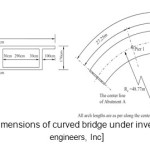 |
Figure 3: Plans and dimensions of curved bridge under investigation [Berger / Adam engineers, Inc] Click here to View figure |
 |
|
![Figure 5 - A) cross columns, B) cross-drilled piles [Berger / Adam engineers, Inc]](http://www.cwejournal.org/wp-content/uploads/2015/06/Vol10_Spe_Inves_Moha_Fig5-150x150.jpg) |
|
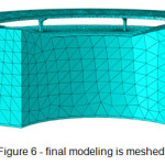
Earthquake record in the history of the 1994 Northridge Earthquake Accelerogram is applied in chord and Radius direction into bridge. However, due to the large volume of research and time taking analysis for calculation, we used High volatility, i.e., we used Northridge earthquake records in first 20 seconds. In order to prevent reflected waves from the boundaries of the soil, we used attractor elements. Also horizontal expansion of soil from the piles in the horizontal direction was equal to the length of piles. Finally, the modeling was according to the figure 6.
 |
|
Table 1: soil property in location
|
Type of soil |
The type of Alluvial is mud sand with medium density |
|
Angle of internal friction (Φ) |
34 (deg) |
|
Modulus of elasticity (Es) |
350 (kg/cm2) |
|
Poisson's ratio |
0.3 |
|
Specific weight |
1700 E-6(kg/cm3) |
Table 2: Characteristics of seismic isolator DCFP
|
Isolator |
Re (Cm) |
ξeff |
W (Kg) |
Keff (Kg/Cm) |
|
Abutment |
287 |
0.34 |
103×112.299 |
850 |
|
Piles |
287 |
0.34 |
103×236.258 |
1766 |
Table 3: Prestressed concrete specifications
|
Compressive strength (F'c) |
350 (kg/cm2) |
|
Strain like maximum stress (εo) |
0.002 |
|
Compressive strength at the moment of rupture (Fu) |
250 (kg/cm2) |
|
Strain at the moment of rupture (εcu) |
0.003 |
|
Modulus of elasticity (Ec) |
3.2E5 (kg/cm2) |
|
Poisson's ratio |
0.2 |
|
Specific weight |
2300E -6 (kg/cm3) |
Results
In this study, In order to evaluate the influence of using the DCFP on deck stress and base shear of the curved bridge, the modeling on modes (with DCFP and without DCFP) of bridge had been analyzed in the nonlinear time history analysis. It should be noted that, in the process of analysis for both modes, first the environment was exposed to the Static force of gravity and then the earthquake excitation were applied. Eventually the driven results from both case were compared with each other. Table 4 indicates the characteristics of the points on deck, which were exposed to the most stress.
Table4: The properties of investigated points
|
The No. of point |
The distance from the source deck (Cm) |
|
1 |
0 |
|
2 |
1362.5 |
|
3 |
2725 |
|
4 |
4400 |
|
5 |
6075 |
|
6 |
7437.5 |
|
7 |
8800 |
Figure 7 shows the stress time history curve related to point 3 of non isolated bridge. According to this diagram, the maximum stress is 140.53 Kg/cm2 in this point that happens in 9.98 sec. By investigating the stress curves for the rest of the points in both modes (with DCFP and without DCFP) and extracting the maximum stress at these areas, the maximum stress curves will be like figure 8.
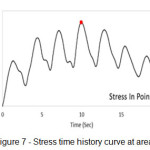 |
Figure 7: Stress time history curve at area 3 Click here to View figure |
 |
|
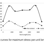
According to the figure 8, table 5 will be obtained. In this table the maximum stress in each of the point on the bridge deck is specified.
Table5: amount of average stress reduction in each of points on the bridge deck
|
The No. of point |
the distance of point (Cm) |
The maximum stress in bridge with no DCFP (Kg/Cm2) |
The maximum stress in bridge with DCFP (Kg/Cm2) |
Reduction percent |
|
1 |
0 |
66.26 |
31.15 |
53 |
|
2 |
1362.5 |
178.62 |
67.14 |
62 |
|
3 |
2725 |
140.53 |
47.80 |
66 |
|
4 |
4400 |
147.90 |
25.75 |
83 |
|
5 |
6075 |
150.30 |
54.04 |
64 |
|
6 |
7437.5 |
181.66 |
55.82 |
69 |
|
7 |
8800 |
63.03 |
34.43 |
45 |
By investigating the results shown in Table 5, we will understand that the maximum stress on bridge deck in the bridges with DCFP is less than the bridge with no DCFP. By averaging the results, its amount will be 63%. In the other word, it can be concluded that using the DCFP in curved bridge, will reduce the stress in bridge deck to 63%. However, the structure specifications and strength of materials in both bridges are the same.
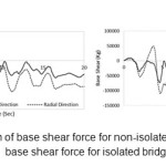
The force diagram of base shear, caused by earthquake for both isolated and non-isolated bridge in chord and radius direction is illustrated in figure 9.
 |
|
According to the above diagrams table 6 will be obtained. According to the given results in the table shear force in bridge with isolator 63% in chord direction and 74 % in radius, is less than that the bridge with no isolator.
Table6: amount of base shear reduction in each of case
|
Direction |
base shear force for non isolated bridge maximum (Kg) |
base shear force for isolated bridge maximum (Kg) |
The percent of reduction |
|
Chord |
309139.4 |
113418.04 |
63 |
|
Radius |
422766.9 |
109788.16 |
74 |
Discussion
By evaluating the results, driven from this analyze, it can be understood that the maximum stress in length of the isolated bridge deck has a significant reduction. This indicates that, seismic isolator unlike the theory of increasing the strength of materials, will lead to low damage in earthquake by reducing the structure demand low earthquake force.
Using seismic isolator system at the bridge structure reduces the base shear force. It indicates the reduction of structural demand which cause structural design with smaller sections and lower cost.
In general, according to the given results, we can conclude that using seismic isolation system in the bridge structures will reduce bridge stress, base shear force and improve its performance against earthquake excitation, and this will increase the chance of using this important structure after earthquake.
Acknowledgements
I would like to express my very great appreciation to Dr Mohammad-Ali Lotfollahi-Yaghin for his valuable and constructive suggestions during the planning and development of this research work. His willingness to give his time so generously has been very much appreciated.
References
- Ates, S. and Constantinou, MC. (2010), “Example of application of response history analysis for seismically isolated curved bridges on drilled shaft with springs representing soil,”Soil Dynamics and Earthquake Engineering, doi:10.1016/ j.soildyn.2010.09.002.
- Bahar, A . And Sadrara, M. (1391), "Performance evaluation of curved bridges with seismic base isolation system," Second National Conference on Earthquake, Geotechnical and structures, Islamic Azad University, Science and Research Branch, Tehran, Iran, December.
- Berger / Adam engineers, Inc., (1996), “Federal highway administration seismic design course,”design example No. 6, Publication no. FHWA-SA-98-011 and Barcode no. PB97142111.
- Constantinou, M.C. (2004), “Friction Pendulum double concave bearing,” Report NEES, available at: http://nees.buffalo.edu/docs/dec304/FP-DC%20Report-DEMO.pdf.
- Constantinou, M.C. and Whittaker, A.S. and Fenz, D.M. and Apostolakis, G. (2007), “Seismic isolation of bridges,” Report submitted to the State of California Department of Transportation.
- DeSantiago, E. and Mohammadi, J. and Albaijat, HMO. (2005), “Analysis of horizontally curved bridges using simple finite-element models,” The Practice Periodical on Structural Design and Construction, 1, (1), pp 18–21.
- Olmos, B.A. and Roesset, J.M. (2008), “Soil structure interaction effects on base isolated bridges,” 14th World Conf. On Earthquake Engineering, China, pp.
- Seed, H.B. and Idriss, I.M. (1969), “The influence of soil conditions on ground motion during earthquake,”Journal of soil mechanics and foundation, 94, (SM1), PP 99-137.
- Tongaonkar, N.P. and Jangid, R.S. (2003), “Seismic response of isolated bridges with soil- structure interaction,” Soil Dynamics and Earthquake Engineering, 23, PP 287-302.
- Wolf, J.P. (1987), “Dynamic soil- structure interaction,”Prentice- hall international series in civil engineering and engineering mechanics, ISBN 0 13 221565 9, United States of America.